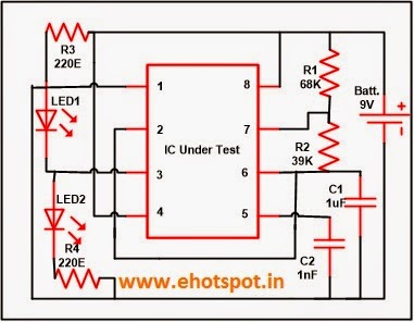
555 Ic Tester Circuit Diagram
Simple 555 tester circuit diagram How does ne555 timer circuit work 555 timer ic-block diagram-working-pin out configuration-data sheet
555 IC Tester Circuit ~ Electronics Hotspot
Tester ttl cmos bytes Circuit tester op amp ic test simple diagram cheap schematic ics bc548 lm741 figure lm358 easy radio eleccircuit Timer 555 ne555 datasheet pinout block does ic eleccircuit flop lm555 voltage
555 circuit tester diagram ic simple timer circuits schematic test chip electronic diagrams ic555 pwm control timers follows complete
Introduction to the 555 timerTester ic timer circuit Tester ic circuit blogthis email twitterCircuit ic timer tester components used.
Timer 555 circuit schematic electronic circuits control ic relay using simple next charger board timing basic schematics battery diagrams chooseTester polarity probe circuits ic eleccircuit schematics beginners vhf Ic circuit tester blogthis email twitter led read555 timer diagram ic block circuit ne555 controller configuration op working pins flip flop pwm discharge electrical resistive.

Build your own simple ic tester applied to standard ttl or cmos ic
555 741 tester timer op amp ics circuit diagram circuits fig555 timer ic tester circuit 555 timer ic diagram block ne555 internal flop flip wikipedia transistorTimer 555 schematic.
555 ic tester circuit ~ electronics hotspotFree circuit diagrams: ic555 tester circuit 555 ic tester circuit ~ electronics hotspot555 timer ne555 engineeering.

555 timer ic
555 timer circuit using light dancing circuits diagram chip pcb easyeda 555timer pulse ne555 projects lm555 time astable cloud softwareThe op-amp ic tester circuit Ne555 eleccircuit ics multimeterSimple 555 ic tester circuit diagram.
555 ic tester circuit ~ electronics hotspotTimer ic 555 tester Dancing light using 555 timerTimer graham lambert.

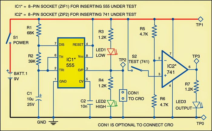
Tester for 555 timer and 741 op-amp ics
The op-amp ic tester circuit .
.


555 IC Tester Circuit ~ Electronics Hotspot

Simple 555 IC Tester Circuit Diagram | ElecCircuit.com

Free Circuit Diagrams: IC555 Tester Circuit

Tester for 555 Timer and 741 Op-amp ICs | Expert Circuits

timer ic 555 tester | Best Engineering Projects

555 IC Tester Circuit ~ Electronics Hotspot

The Op-amp IC tester circuit

How does NE555 timer circuit work | Datasheet | Pinout | ElecCircuit.com